What panel cutting optimization actually does
Panel cutting optimization is the process of arranging a set of rectangular parts onto a set of rectangular sheets to minimize waste, reduce cut count, and produce a layout that can be executed in production.
The inputs are:
- A list of parts, each with a width, length, and quantity
- A list of sheet stock, each with dimensions and an available count
- Constraints that affect how parts can be positioned (kerf, grain direction, rotation limits)
The output is:
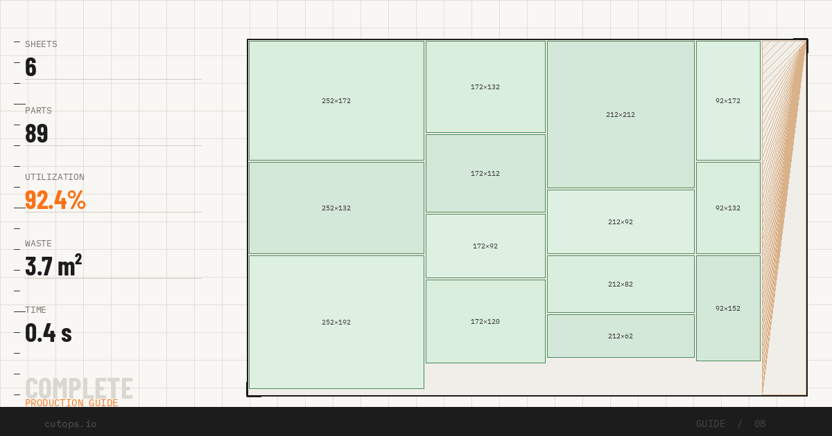
- A layout showing where each part sits on each sheet
- Utilization metrics per sheet and overall
- A cut sequence that can be handed to an operator or loaded into a saw
The goal is not the most mathematically efficient packing. It is the most practical layout for your shop's constraints.
Constraint setup: the step most teams skip
Optimization runs without constraints are fast and produce high-utilization numbers. They also frequently produce layouts that cannot be cut as shown, because real shops have constraints that the optimizer does not know about unless you tell it.
Kerf
Kerf is the material removed by the saw blade on each cut. A 3.2 mm blade kerf is small per cut but significant across 80 cuts on a large job. Optimizers that ignore kerf produce layouts where parts are planned to fit but do not physically fit when cut.
Set kerf before the first run. Enter the blade thickness for your primary cutting tool. CutOps applies this value to every cut boundary in the layout automatically.
Grain direction
Sheet materials with visible grain — hardwood plywood, MDF with face veneers, laminated melamine — require parts to be oriented so the grain runs consistently. A side panel rotated 90 degrees for better nesting creates a component that fails visual inspection.
Set grain direction locks per part for any component where rotation would affect appearance or structural performance. Leave rotation enabled for parts where it does not matter — shelves, hidden blocking, backs — to give the optimizer more flexibility.
Rotation limits
Some parts are square or nearly square and can rotate without visible impact. Others have a specific length-to-width relationship that must be preserved. Set rotation to "no rotation" on any part where position matters.
Running your first optimization
After entering parts, stock, and constraints, run the optimizer. Review three things before doing anything else:
Utilization percentage. This tells you what fraction of sheet area is covered by parts. A well-constrained job on appropriate stock typically runs 80–92% utilization. Below 75%, investigate whether part grouping or stock selection can improve the result.
Sheet count. Does the layout use the number of sheets you estimated? Significant divergence usually indicates a constraint or stock entry issue rather than an optimizer error.
Unplaced parts. If any parts do not appear in the layout, the optimizer could not place them on the available stock. Common causes: a part larger than any available sheet, stock quantity set too low, or an overly restrictive constraint combination.
Strategy comparison: why one run is not enough
Most optimization problems have more than one valid solution. Different layout strategies make different tradeoffs:
- Utilization-first strategies minimize waste area but may produce complex cut sequences with many small crosscuts
- Cut-simplicity strategies reduce the number of cuts and the handling required, at the cost of slightly lower utilization
- Balanced strategies attempt to optimize both dimensions simultaneously
Run at least two strategies on every job. Compare the results side by side:
| Metric | Strategy A | Strategy B | | ------------------- | ---------- | ---------- | | Sheets used | 8 | 9 | | Cuts per sheet | 22 | 14 | | Average utilization | 91% | 83% |
Strategy A uses fewer sheets. Strategy B requires significantly less operator time per sheet. Depending on your labor cost and material cost, either choice could be the right one.
Reading the layout output
After optimization, review the visual layout for each sheet before exporting.
Check part labels. Each part in the layout should be labeled in a way an operator can identify without referring to a separate document. If parts are labeled only by internal ID numbers, add human-readable names before exporting.
Check cut boundaries. Parts should not be positioned at the very edge of a sheet without accounting for sheet edge quality. If your stock has edge defects or requires a rip cut on one side, shift parts inward by the trim allowance.
Check grouping logic. Parts that belong to the same assembly should ideally appear on the same sheet or adjacent sheets where possible. This simplifies sorting and reduces the risk of assembly errors.
Exporting for production
A panel cutting optimization layout is only useful if it can be acted on by the people who do the cutting. Export in the format that matches your production workflow.
PDF is the most portable format for production communication. Operators can print and mark up a PDF layout without needing access to the optimization tool.
CSV provides structured part data for CNC panel saws and machining centers that accept cut list file imports.
PNG gives a quick visual snapshot that can be attached to a job packet or shared digitally with the production team.
JSON enables downstream integration with shop management systems or custom tooling.
Export all formats you regularly use from the same workspace. There is no value in re-entering the same layout in a second tool.
Common optimization errors and how to fix them
High sheet count vs. estimate. Usually caused by grain direction constraints that prevent effective nesting. Check which parts have grain locks enabled and whether any could be relaxed.
Low utilization on a large job. Often caused by a small number of large parts that cannot share a sheet with other parts. Separate these into their own stock run and optimize the remaining parts together.
Cut sequence is too complex. Reduce optimization depth or switch to a cut-simplicity strategy. Fewer total cuts usually reduces mistakes on the floor even when utilization is slightly lower.
Unplaced parts at end of run. Increase available sheet count or check whether any part dimension exceeds the stock dimensions you entered. A 1200 mm part cannot be placed on a 1220 mm sheet with kerf applied unless the sheet is at least 1200 + kerf wide.
Run panel cutting optimization in CutOps — free, browser-based, no installation required.